Wireless Power Transfer Schematic Diagram Circuit Diagram Before diving into building let me give you a basic idea on working of wireless power transmission. How Wireless Power Transmission Works. Magnetic inductive coupling principle is used in the working of wireless power transmission. Like all transfer devices there will be a transmitter and receiver and this uses basic principle to transmit energy. Simple wireless power transmission circuit for school projects with circuit diagram. This circuit is used to demonstrate the concept of wireless power transf

It also offers a wide range of charging solutions in an efficient way. The power delivery ranges up to 200W, with very low loss of power transfer. A major benefit of wireless power transmission is that the product life can be increased by preventing the physical damages due to charger insertion across the connectors or the ports. Multiple

Simple Wireless Power Transmission Circuit to Glow an LED Circuit Diagram
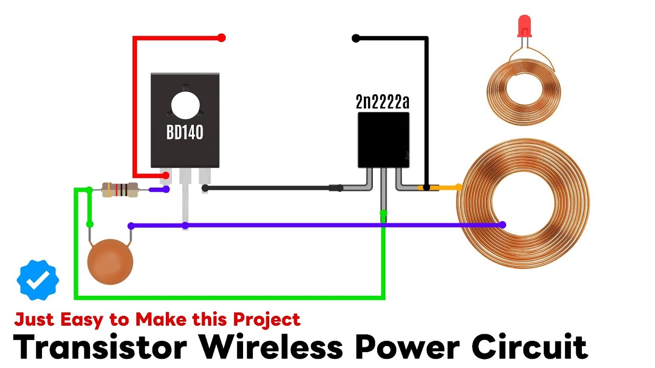
In recent years, wireless charging of consumer electronic devices has become common. The simplest wireless circuit consists of only a handful of parts. At the very least, it consists of a power source, a transistor, an antenna coil, a receiver coil, and of course something to power on the receiver end also known as a load.

Simple Wireless Power: Make wireless electricity easy with this simple DIY! This project will use the principle of magnetic inductive coupling to transfer electricity between two separate coils. I enjoy making and reverse engineering simple electronic circuits and devices. I hope you enjoy my instuctables, and more will be coming out soon A Wireless Power Transmission Circuit is an electronic circuit designed to transfer electrical energy from a power source to a target device without the need for physical connections like wires. Wireless power transmission is based on technologies that use electromagnetic fields to transmit power over short or long distances.

Simple Wireless Power : 8 Steps Circuit Diagram
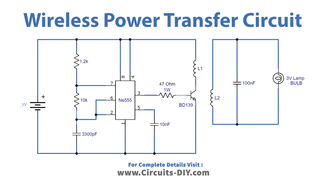
Here is the simple Wireless Power Transmitter and Receiver Circuit Designed with few affordable electronic components. Both Transmitter and Receiver have Enameled Copper coil winding, A Square wave oscillator and copper coil acts as power transmitter. Copper coil and Bridge Rectifier circuit acts as Receiver.
In this tutorial, we will build a wireless power transmitter and receiver that can transmit enough power to charge a 3.7V battery. How Wireless Power Transmission Works. In a wireless power transmitter, incoming power is converted to a high frequency oscillating signal. This oscillating current is then sent to a wire coil.