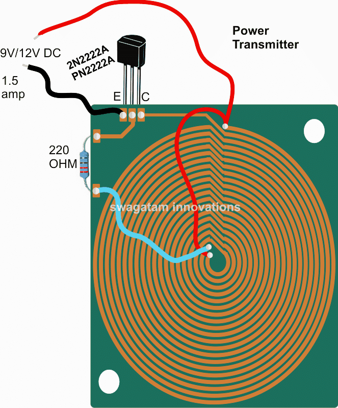
Wireless Cellphone Battery Charger Circuit Circuit Diagram How the Circuit Works. The wireless battery charger is developed using two circuits, as shown in the diagram. : Transmitter Circuit; Receiver Circuit; Transmitter. The first one is the transmitter circuit that generates voltage wirelessly. It comprises an oscillator circuit, a transmitter coil, and a DC power source. Diversity Of Trends In Wireless Power Charging At Apec 2018 Edn. Wireless Mobile Charger Circuit Diagram Engineering Projects. Fundamental Dc To Circuit Diagram Of A Wireless Charging System Scientific. Eval 2kw 48v Char P7 Lead Acid Li Ion Battery Charger Evaluation Board. Mobile Phone Battery Charger Circuit Diagram
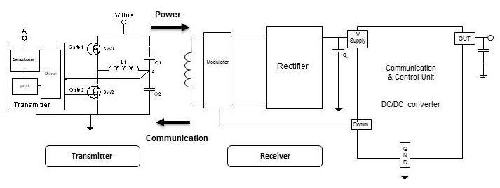
Find every electronics circuit diagram here, Categorized Electronic Circuits and Electronic Projects with well explained operation and how to make it procedure and then New Circuits every day, Enjoy and Discover electronics. In Wireless Gadget charger circuit we used BD139 NPN transistor as per the datasheet claim it can handle 1.5A current With that in mind, let's take a closer look at a circuit diagram for wireless mobile charging. The diagram consists of a receiving side, consisting of a primary control unit, an oscillator, a bridge rectifier, and a storage capacitor. The sending side includes a transmitter, which generates high frequency alternating current (AC) electricity

Wireless Gadgets Charger Circuit Circuit Diagram
Wireless Mobile Charging is one of the trending topics in the field of electronics thus we also decided to build a Wireless Mobile Charger Circuit Diagram using various commonly available components. The project Wireless Mobile Charger Circuit Diagram posted here can deliver 271mA at 5.2V so you charge mobile phones and also can be used to drive low power loads such as LED 1 and LED 2 as shown
Wireless charging is the future of powering devices, eliminating the need for tangled cords and cables. Wireless Battery Charger Circuit Diagrams are a great way to learn how to build your own wireless charger, so that you can ditch the wires and enjoy the convenience of wire-free power. These are very important to wireless charging circuit. We need to use AC to drive the transmitter coil, since the receiver can only generate electric signal when there is a alternating magnetic field. At last we have the circuit diagram for an indcutor(or a coil), it is like four half circles, as shown in the third picture. An inductor has The modified wireless cellphone charger circuit diagram and the prototype images can be witnessed below: Wireless Mobile phone charger circuit Detailed Working Description. We have got the transmitter coil which is designed as a center-tapped transformer. What this means is that there is a center tap that connects to the positive supply voltage
