Temperature Control System Circuit Diagram The project "Cute Temperature Controller" by Shree.Bera Somnath. Thanks for the simple design. But the price of the Sensor TMP 35/36 is extremely prohibitive and is not easily available. I hunted thru many suppliers and finally got a few at choking prices. Until lately, I stuck to LM35 and the like.
Also the cheap types are not reliable at all, because their accuracy is not consistent. The diy temperature controller circuit presented in this article is super simple in design, yet is able to produce reasonably accurate and consistent temperature control over a range of 40 to 125 degrees Celsius, which is fully adjustable. Temperature control system component list. The temperature measured using LM35 is compared with the reference value. If the measured temperature is higher than the reference value by 1ºC, the heater is switched off, and if the measured temperature is lower than the reference value by 1ºC, the heater is switched on.

Temperature Controlled Switch using LM35, LM358 Circuit Diagram
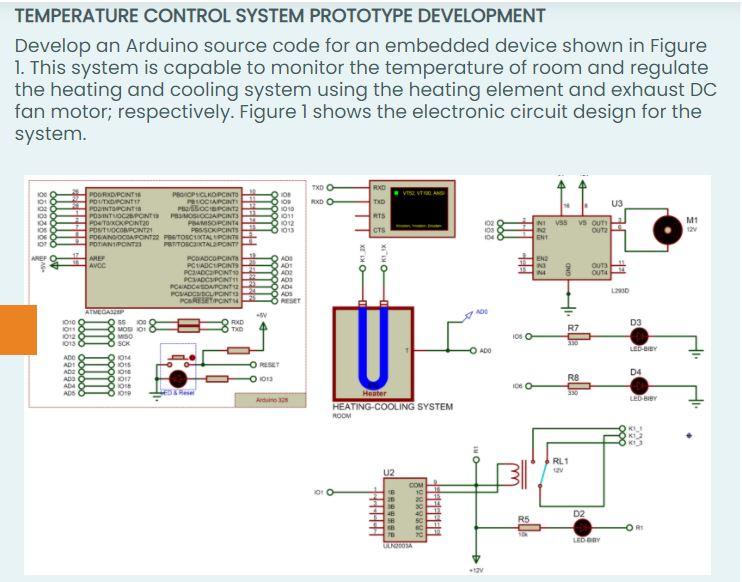
LM35 Temperature Sensor: Connect the VCC pin of the LM35 to the Arduino's 5V pin, GND to ground, and the output to the analog pin A0.This sensor will send temperature readings to the Arduino. Heating Element: Connect the positive terminal of the 12V power supply to one of the terminal of the heating element.Connect the other terminal of the heating element to the drain of the MOSFET
* Controllers come in various varieties: on-off, proportional, and PID controllers can all provide effective temperature regulation at cost-effectiveness; however on-off controllers can create temperature oscillations due to simple design features, while proportional controllers offer smoother control while PID delivers greater precision and The following are the basic steps and relevant points for designing a temperature control system based on PLC: System requirements analysis; Determine the control object: for example, heating furnace, reactor, air conditioning system, etc., clarify its requirements for temperature control, including temperature range, accuracy, heating/cooling rate, etc. This article will show you how to build a model of such temperature control system using minimum components and without any complex circuit. First, let us learn few terms. Control System. Control System is a combination of various physical elements connected in such a manner so as to regulate/direct/command itself or some other device/system
How to Build a Temperature Controller: A Step Circuit Diagram
Testing and calibration are an integral component to ensure the temperature controller operates as intended: Initial Power-On and Check of Basic Functionality. Calibrating Sensor Values to Match Temperature Values. Fininshing Tuning Control Parameters by Adjusting PID Parameters in Order to Achieve Optimize Temperature Control. A Brief Note on Temperature Controlled Switch . As the name suggests, a Temperature Controlled Switch is a device or circuit, which is activated based on the Temperature. Any Temperature Controlled Switch consists of three parts: Sensor, main control unit and the switch. The following image shows a commercially available Temperature Controlled
