Stop IoT Solution for Battery Management Circuit Diagram Do it yourself battery management system for Lithium ion battery packs/cells - stuartpittaway/diyBMS. A DIY Powerwall is the DIY construction of a pack of battery cells to create an energy store which can be used via inverters to power electrical items in the home. Generally cells are salvaged/second hand, and typically use Lithium 18650 cells. A battery pack built together with a battery management system with an external communication data bus is a smart battery pack. A smart battery pack must be charged by a smart battery charger. BMS circuit is used in most of rechargable electronics including smartphone, electric cars, Electric cycle, & etc
By following this comprehensive guide, you'll have all the knowledge and tools necessary to build a safe, reliable, and high-performance 18650 battery pack with BMS for your DIY projects. Embrace the DIY spirit, prioritize safety, and enjoy the satisfaction of powering your creations with a custom-built battery pack. The recent advancement of battery technology has encouraged newcomers to learn about BMS system and there designing. In this post I will provide a beginners guide towards BMS systems and we will also make a DIY BMS system(for monitoring the battery cell voltage). BMS - Battery management system. That's why we have decided to design and build a DIY wireless battery monitoring system, which can be used with the existing BMS. For this project we have chosen the AD7280 Lithium-Ion Battery Monitoring chip from Analog Devices, and for wireless connectivity we have chosen our favourite ESP32. The AD7280 is capable of monitoring up to 6S

Battery Management System for lithium Circuit Diagram
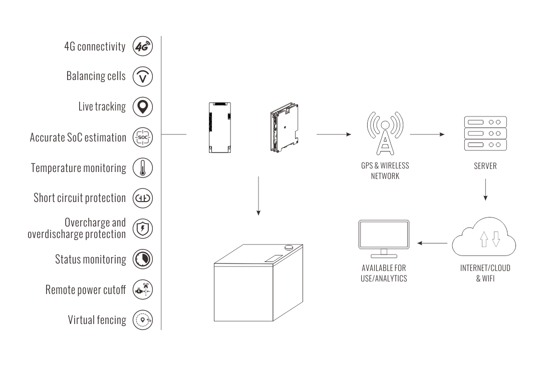
Brief Overview of the Project. In this project, we will build a Smart IoT Battery Management System Using ESP32, allowing users to track real-time battery voltage, percentage, and temperature.The system uses an ESP32 microcontroller to read battery voltage via a voltage divider circuit and monitors temperature using an NTC thermistor.A relay module is integrated to automatically cut off The battery cells can swell and even explode from overcharging, and a deep discharge can make the battery fail. That's why these batteries should go together with a battery management system unit or BMS. This will control the voltage and current from the battery and keep them safe. Once our battery is soldered together, we need to measure the voltages across the series cells with a multimeter. You should have 14.8 volts for battery positive, 3.7V volts, 7.4V volts, and 11.1 volts. There are 5 connections for a 4S balance plug: one for battery positive or cell #4, one for negative, cell #1, cell #2, and cell #3.
