Step by step guide Circuit Diagram Sound Level Meter With Arduino: Previously three different versions of Sound Level Meter (From hereinafter as SLM) circuits are introduced. All these circuits are mainly utilizing op-amps (NE5534, TL071) and LM3915 bar/dot display driver IC. You can see the details of these SLMs i… Hello everyone, have come back to my channel. In today's video I will make audio level indicator with LM3915 ic. This is a very common simple circuit. There

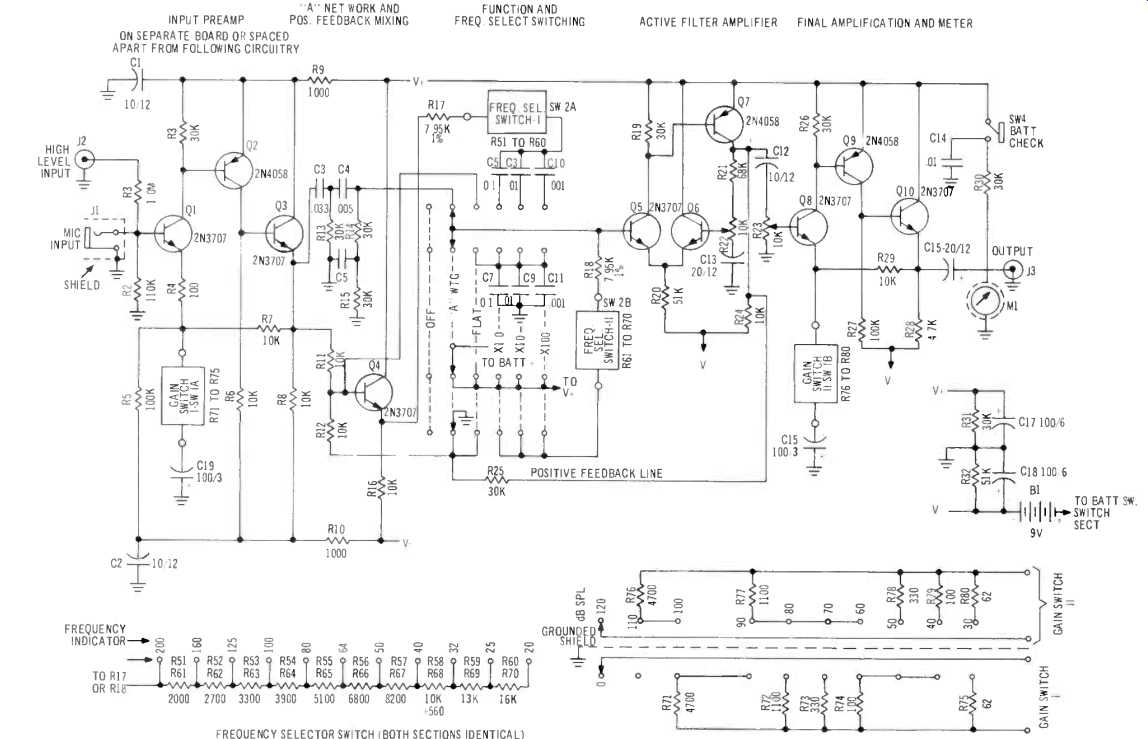
Learn how to build a simple sound level indicator circuit, similar to a VU meter, using basic electronic components! In this step-by-step tutorial, I'll guid This nifty sound level meter is a perfect one chip replacement for the standard analog meters. It is completely solid state and will never wear out. The whole circuit is based on the LM3915 audio level IC and uses only a few external components. Circuit diagram. Original Schematic. Parts C1 2.2uF 25V Electrolytic Capacitor R1 1K 1/4W Resistor A Sound Level Meter To convert the kit into a useful test instrument, I designed and built a sound level meter (see Photo 1). I opted to call my design the Model 527, because I wanted to keep track of all the drawings and photos. (It may or may not be a TDL Technology product.) The cast aluminum enclosure measures 6.73" × 4.76" × 2.17."
How to build Sound Level Meter Circuit Diagram
Sound Level Meter: This is a sound level meter circuit consisting of an electret condenser Mic, pre-amplifier circuit using NE5534/TL071 and LM3915 bar/dot display driver chip. According to the sound pressure captured by Mic, this device shows sound levels with LEDs. … A simple sound level circuit made using LM3915 and few other basic components.Dreams Become Real by Kevin MacLeod is licensed under a Creative Commons Attrib This nifty sound level meter is a perfect one chip replacement for the standard analog meters. It is completely solid state and will never wear out. The whole circuit is based on the LM3915 audio level IC and uses only a few external components.

To build a Sound Pressure Level Meter Circuit using IC CA3140 following are the steps to follow for assembling. Gather all the components as mentioned in the above circuit diagram. Connect pin 2 of IC1 CA3140 to one terminal of R5, and connect the other terminal of R5 to the positive of capacitor C3 and connect the negative of capacitor to GND.

LED Sound Level Meter using LM3915 Circuit Diagram
Sound Level Meter Circuit Diagram. If you are learning to be a communication engineer, playing with audio circuits is very important. This sound level meter is a simple hobby circuit to start with. You should build amplifier circuits and filter circuits to get a good grip on the subject.