Simultaneous Estimation of Vehicle Sideslip Circuit Diagram The vehicle's construction focused on integrating components into a cohesive, user-friendly system. The chassis was designed to house the hardware securely while ensuring mobility over various terrains. The onboard system operates in two modes: Access Point Mode: Creates a local network for control without needing external internet.
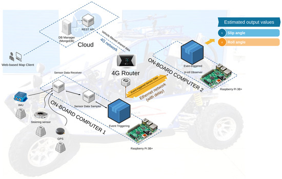
The project aims to create a versatile remotely operated unmanned ground vehicle system that integrates various technologies such as IoT, machine learning, and real-time data transmission. This system is designed to be highly adaptable and capable of performing tasks such as remote surveillance, environmental monitoring, and rapid response to In an age where the Internet of Things (IoT) is revolutionizing the way we interact with and control our surroundings, the convergence of technology and innovation has given birth to remarkable projects. One such project that epitomizes the power of IoT and embedded systems is the "Design and Implementation of a Wi-Fi Controlled Car Using the vehicle. Our approach simplifies car control and opens up possibilities for more user-friendly interactions in areas like human-machine interfaces and the Internet of Things (IoT). Obstacle Avoidance We've enhanced safety by incorporating an automatic obstacle detection system into our design, preventing potential hazards.

Controlled Unmanned Vehicle: a Revolutionary IoT ... Circuit Diagram
This paper proposes an intelligent transportation system based on Internet of Things technology. This paper presents the optimal design structure of intelligent transportation system based on Overall, this paper will provide a comprehensive overview of the topic of IoT Command Remote Control Vehicles, including their design, implementation, challenges, and applications. Discover the

The RC Vehicle and Firmware Like many RIOTOUS projects, the circuit is very simple, consisting of a 3.3V linear regulator circuit, an ESP-01 Wi-Fi module, and a PIC16F1516 microcontroller. The motors are controlled using the L9110S Dual Motor Controller, which at its core is essentially an H bridge circuit.

Design and implementation of electric vehicle with autonomous motion ... Circuit Diagram
The speed control and steering control are then set based on speed control PWM signal (SPCPWM) and the steering control PWM signal (STCPWM). The detailed descriptions provided in the flow diagram. The system determines the vehicle's speed and direction using LIDAR distance, proximity sensor readings, and calculated steering angle.

Remotely controlled car - IoT based project using Wi-Fi Module and MIT App Inventor with intuitive control. A step-by-step guide! 11338 views • 4 respects. app. toys. cars. remote control. internet of things. robots. Components and supplies. 1. Li-Polymer Battery, 150mAh. 1. Arduino UNO. 4. DC Motor, 12 V. 1. NodeMCU ESP8266 Breakout