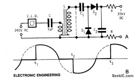
SIMPLEHIGHVOLTAGESUPPLY Circuit Diagram A voltage amplifier circuit is a circuit that amplifies the input voltage to a higher voltage. So, for example, if we input 1V into the circuit, we can get 10V as output if we set the circuit for a gain of 10. Voltage amplifiers, many times, are built with op amp circuits. This simple circuit is built using an IC 555 circuit for boosting USB 5V to 24V, or any other desired level. The same design can be used for boosting a 3.7 V to 24 V from a Li-Ion cell. Let's assume we have the following parameters required for the above circuit: Important Parameters: Input Voltage (Vin): 5V; Output Voltage (Vout): 24V There are many ways to create high-voltages and pulses; the Marx generator is a simple one in concept and practice. Low-voltage designs with rails in the single digits get a lot of attention these days for reasons I don't need to detail to this audience. Still, there are many situations where rails at hundreds of volts are needed, such as EVs.

The electronic circuit design process involves the creation of electronic circuits, which can vary from individual transistors within an integrated circuit to more complex systems. While simple circuits can often be designed by a single individual, only some projects require the involvement of a dedicated circuit designer. AC high voltage source, with an output value of 5 to 10 thousand volts. This assembly consists of a driver circuit and a flyback transformer from an old TV. In my case it is a "Plasma Speaker" device I have made before. Also you can create a simpler driver for example with 555 IC, for which is also given the link to the schematic below.

How to Build a Boost Converter Circuit: Explained with Calculations Circuit Diagram
Connect either one wire from the primary (the low voltage side) to one terminal of the battery (don't worry, you can connect it any way round). Then bring two secondary wires (the high voltage side) very close to each other (about 2 mm) and then tap the other primary wire to the other terminal of the battery. The output current of the circuit is around 20mA. The circuit can work for any application requiring a high voltage & low current input. The output depends on the inductive coil used. For example, with a 220μH coil, the max output of the circuit will be around 40V DC. Similarly, a 470μH coil can yield up to 70V DC.

High Power 10 kv Generator Circuit. If powered with a 30 V power input, the circuit detailed below can provide a high voltage which range from 0 to 3 kV (type 2 an even provide from 0----10 kV. NAND gates N1----N3 are wired like an astable multivibrator (AMV), which powers the darlington transistors T1/T2 with a 20kHz souarewave frequency. Simple 5 V to 12V Boost Converter Circuit using 2N2222 Correction: L1 = 330 uH. In the first concept as shown in the figure above, the input DC supply can be anywhere between 3 V and 5 V. We can adjust the output voltage to 12 V or some other desired voltage by tweaking the zener diode D2.
