Schematic of fabricated wireless power transfer circuit Circuit Diagram Working of the Wireless Electricity Transfer Circuit Both the circuits are constructed on the breadboard and powered using a 1.5V battery. The circuit can't be used for more than 1.5 volt power supply as transistor may heat up for excessive power dissipation. Learn how to create a wireless power transmitter and receiver that can charge a 3.7V battery. The web page explains the principles of wireless power transmission, shows the circuit schematics and provides tips for improving the efficiency. In this project I will show you how to create an appropriate coil and an inverter circuit for a wireless energy transfer system that can easily transfer a power of 20W. Let's get started! Step 1: Watch the Video! The video should give you a basic understanding on how to create the coils and inverter circuit. The next steps will contain

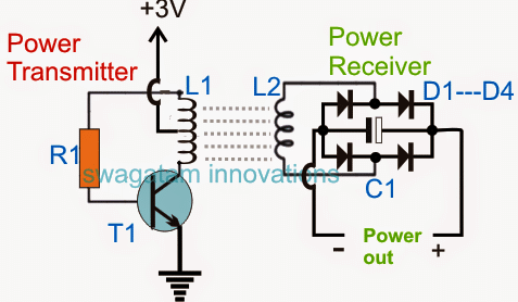
The image above shows a straightforward wireless power transfer circuit consisting of the transmitter stage on the left and the receiver stage on the right side of the design. Both the stages can be seen separated with a significant air gap for the intended shift of electricity.
How to Build a Wireless Power Transmitter Circuit Diagram
But utilizing it in effective way is happening right now, as we know in Wireless Gadget Charging Circuit, wireless battery charging, electric toothbrushes, RFID tags, induction cooking, and wirelessly charging or continuous wireless power transfer in implantable medical devices like artificial cardiac pacemakers, etc.., Lot of innovations need Learn how to design and build a wireless power transmission circuit using a coil, a transistor and a battery. Find out the basics, the working principle and the applications of this technology that reduces environmental impact and risk of shock. Learn how to design a device for wireless power transfer using a high frequency transformer, a coil, a diode and a voltage regulator. Find out the advantages, disadvantages and applications of this emerging technology.

This survey paper provides an in-depth overview and a wide study of wireless power transfer (WPT) systems, based on different technological concepts, and circuits. Further, this paper discusses several techniques to enable efficient and safe operation, standards, and applicable regulations, implementation challenges, commercial systems, and use Wireless Power Transfer System Circuit Diagrams are the key to successful wireless power transmission. These diagrams allow us to understand how data travels between the source and the receiver. With this knowledge, engineers can devise ways to increase efficiency, reduce losses and expand the reach of their wireless system.

Wireless Power Transfer Circuit Working, Advantages and Disadvantages Circuit Diagram
Wireless Electricity Transmission Circuit: This is a simple circuit that can power a light bulb without any wires, at a distance of almost 1 inch! This circuit acts as both, step up Voltage converter and also wireless electricity transmitter and receiver. This is a really easy project to do,…
