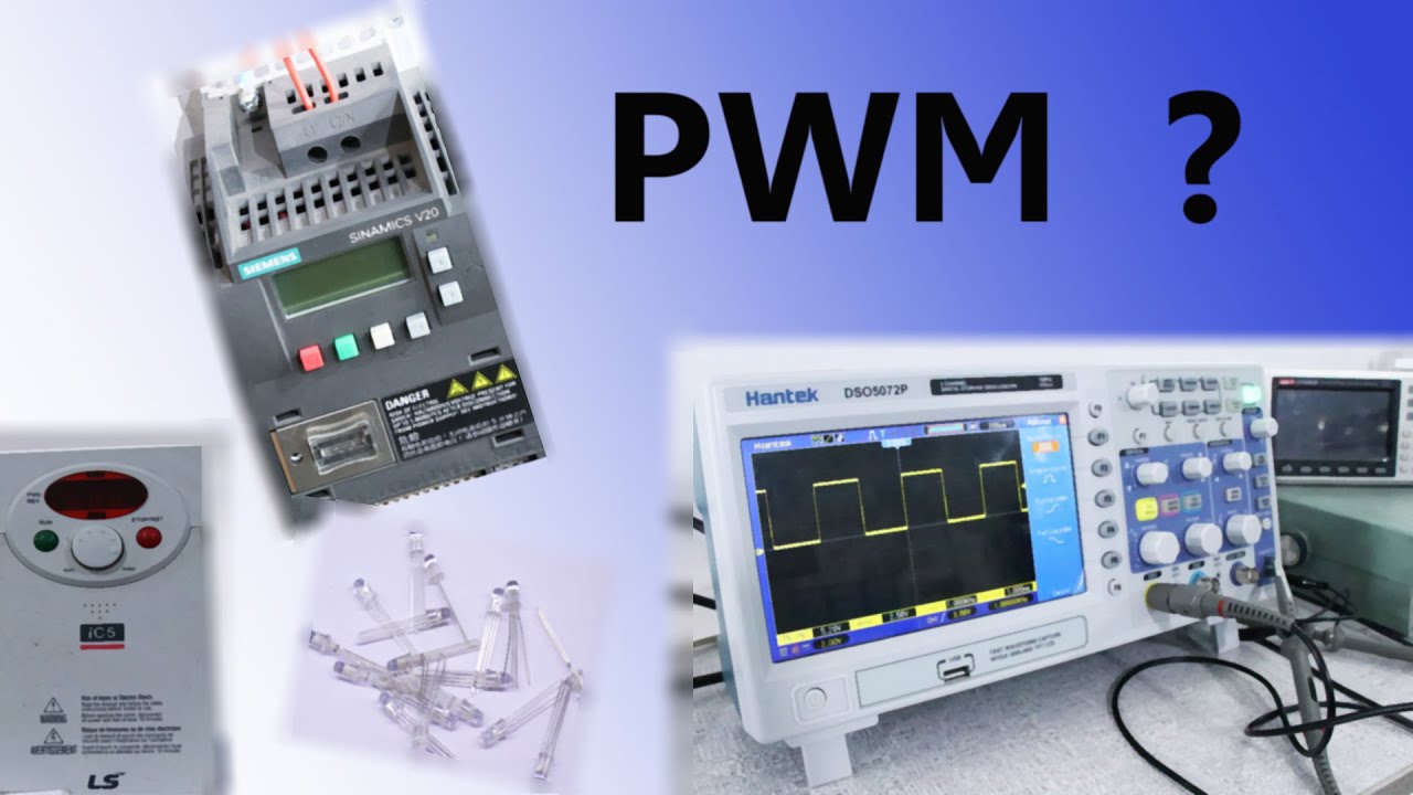
Pulse Width Modulation Circuit Diagram For the test I configured the PWM circuit to have 3 bits of resolution. Which means that the duty value can very from [0..7] and thus it has a range of 8. Looking at the dty value on the third line, you should see that it's value is 4. This represents a 50% duty cycle for a 3-bit PWM circuit. Looking at the next line down shows the pwm output Fig. 10: PWM Waveform on CRO Screen . The complete circuit diagram is given below: Fig. 11: Circuit Diagram of Pulse Width Modulation (PWM) The 1M ohm resistor is used to adjust the amplitude of the sine wave signal generated by the WBO. The amplitude of the sine wave should be adjusted in such a way that it matches with the amplitude of the
Pulse width modulation (PWM) is a technique used to precisely control analog devices with a digital signal. A pulse width modulation signal consists of electronic pulses that are used to mimic a changing analog voltage. In the circuit above, we see a 555 timer configured as an astable oscillator. The 555 timer will generate the pulse width Connect diodes to the variable resistor, as shown in the circuit diagram. Working Explanation. In this circuit, we will use a 555-timer IC for generating PWM. The 555 timers will operate in astable mode and generate continuous square waves at the output.
DIY Circuit Design: Pulse Width Modulation (PWM) Circuit Diagram
2) IC 555 PWM using External Modulation. The second method is slightly complex than the above, and requires an external varying DC on pin#5 (control input) of the IC for implementing the proportionately varying pulse width at the IC output. I have explained the following simple circuit configuration: IC 555 Pinout
Frequency of PWM. The frequency of a pulse width modulation circuit determines the speed or, rather, how fast a PWM takes to complete one period. One Period is full or complete ON and OFF period of a pulse width modulation signal. Normally, the pulse width modulation signals that a lot of microcontrollers generate are around 500 Hz.

How to Generate PWM Using IC 555 (2 Methods Explored) Circuit Diagram
In the PWM technique, the voltage that must be supplied to a DC Motor or an LED is supplied in the form fast switching pulses rather than a continuous analog signal. The "Duty Cycle" and the "Frequency" of the PWM Signal determines the output voltage. Duty Cycle of a PWM Signal describes the amount of time the pulse stays HIGH in one cycle.
So the current flowing through the circuit is flowing 80% of the time during the pulse width and no current flows through the circuit for only 20% of the time. If we further increase the pulse width to 100% you can see what's happened because the pulse width is 100% current is flowing through the circuit 100% of the time.