Pass Active Filters Circuit Diagram Active Low-Pass Filter Design Jim Karki AAP Precision Analog ABSTRACT This report focuses on active low-pass filter design using operational amplifiers. Low-pass filters are commonly used to implement anti-aliasing filters in data acquisition systems. Design of second-order filters is the main topic of consideration.
In an active low pass filter, the peak of the passband of the filter can be much larger than the input voltage signal because there is amplification. For passive low pass filters to be built, all that is required are resistors and capacitors. Active low pass filters require either transistors or op amps to provide amplification to the circuit.
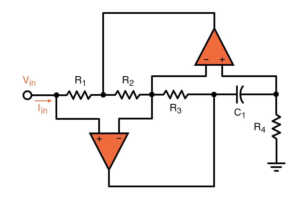
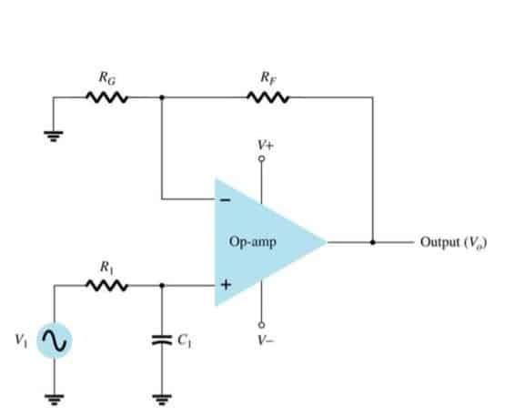
Active Low-Pass Filter with Op-Amps Circuit Diagram
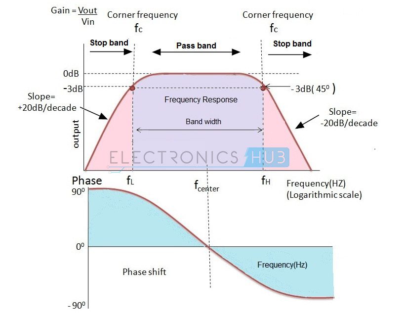
Key learnings: Active Low Pass Filter Definition: An active low pass filter allows low-frequency signals to pass while blocking higher frequencies, essential for various electronic applications.; Component Significance: The use of an operational amplifier (Op-Amp) is critical for adjusting frequency response and enhancing signal quality.; Filter Design: Active low pass filters can be designed
Step-by-step design of Active low pass filter using Op Amplifier. Hi, thanks for watching our video about active filters! In this video we'll walk you through:- How to design, simulate and build active opamp filters- Using range. Bessel low-pass filters, therefore, provide an optimum square-wave transmission behavior. However, the passband gain of a Bessel low-pass filter is not as flat as that of the Butterworth low-pass, and the transition from passband to stopband is by far not as sharp as that of a Tschebyscheff low-pass filter (Figure 16- 9).
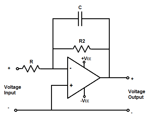
OPAMP101 Low Pass Active Filter Circuit Diagram
View full article: https://www.allaboutcircuits.com/video-tutorials/op-amp-applications-low-pass-and-high-pass-active-filters/In this video we will explore a When used like this in audio applications the active low pass filter is sometimes called a "Bass Boost" filter. Second-order Low Pass Active Filter. As with the passive filter, a first-order low-pass active filter can be converted into a second-order low pass filter simply by using an additional RC network in the input path. The frequency The basic configuration for an active low-pass filter using an operational amplifier is as follows: Place the operational amplifier (op-amp) on a breadboard. Connect a resistor (R) between the input signal source and the non-inverting input ( V in ) of the op-amp.
Second-Order Active High-Pass Filter. If we swap the resistor and capacitor in an RC low-pass filter, we convert the circuit into a CR high-pass filter. We can then cascade two CR high-pass filters to create a second-order CRCR high-pass filter. If we incorporate this passive configuration into the Sallen-Key topology, we have the following: