Need help building a logic calculator We are suppose Circuit Diagram A simple calculator circuit diagram is a schematic representation of the electrical connections and components used to build a basic calculator. It typically includes a power source, input buttons, an output display, and the necessary logic circuitry to perform mathematical operations. The design of the logic circuitry is crucial to the The circuit consists of a 12 digit decimal display where you can insert numbers by pressing buttons 0-9, clear a recent number using the backspace button or clear all digits using the clear all button, just like we observe on a handheld calculator device. I have explained how I made the logic circuit in this post. The basic adding circuit is just that, basic! It consists of a XOR gate and an AND gate to give you the basic output with a carry bit. The XOR gate is short for exclusive or. In a regular OR gate, 0 and 0 equal 0, 1 and 0 equal 1, 1 and 1 equal 1. In an exclusive or gate, 0 and 0 equal 0, 1 and 0 equal 1, 1 and 1 equal 0.
In a simple calculator circuit, the working principle involves using a combination of electronic components such as resistors, capacitors, transistors, and integrated circuits (ICs) to perform basic arithmetic operations. These components are connected in a specific configuration to create the desired calculator functionality. The complexity of a calculator circuit diagram can vary depending on the type of calculator. Simple calculators may have a basic circuit diagram with few components and connections, while scientific calculators may have more complex circuitry to handle advanced mathematical functions and memory storage. Components of a Calculator Circuit Diagram: How To Make A Calculator Using Logic Gates Quora. Applied Digital Logic Exercises Using Fpgas Introduction To. Boolean Algebra Calculator Circuit With Applications. Can You Show Me The Logic Gate Schematic For A Basic Calculator How Does It Work Quora. How Do Logic Gates Calculate Their Output Quora. Controlling A Calculator Display With Logic
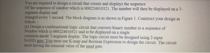
Simple Calculator Circuit Diagram
To design a circuit diagram for a simple calculator, you need to decide on the input and output formats, the number of bits and the functions you want to include. With a little bit of practice, anyone can develop the necessary skills and knowledge required to confidently create their own digital calculator circuits. Reverse Engineering An Early Calculator Chip With Four Phase Logic. Simple Calculator Circuit Diagram Scientific. 0 To 99 Digital Pulse Counter Circuit Homemade Projects. A simple calculator circuit diagram helps make complex calculations quickly and easily. This type of diagram is a visual representation of the components used in a calculator's circuitry, allowing the user to see all the parts that make up the device. It contains logic circuits which are responsible for performing the calculations we use
The 4-bit calculator project consists of three main components: the input circuit, the logic circuit, and the output circuit. The input circuit is responsible for taking in the user input, the logic circuit processes the input and performs the necessary calculations, and the output circuit displays the result on a 7-segment display. The Input