Modeling and Analysis of Frequency Circuit Diagram Fractional-N Frequency Synthesizer PFD Charge Pump N sd[m] ref(t) out(t)e(t) div(t) Σ−Δ Modulator v(t) N[m] Loop Filter Divider VCO Focus on this architecture since it is essentially a "super set" of other synthesizers, including integer-N and fractional-N-If we can design and simulate this structure, we can also

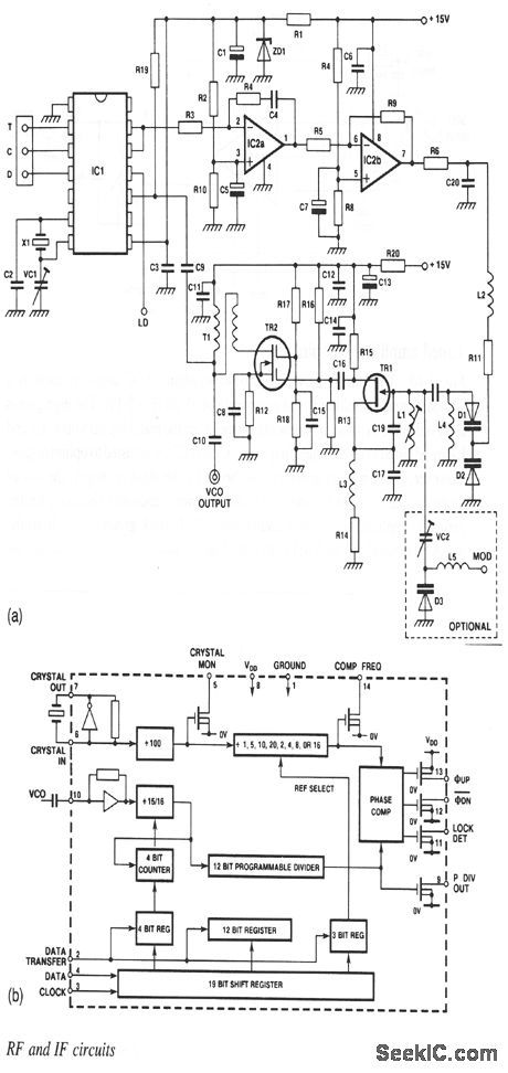
Output of frequency synthesizer can be obtained by either fixing Fr and varying N or varying Fr and fixing N. The RF synthesizer design example mentioned below is for the second case. Channel spacing=Fvco/N or Fr/R. Frequency synthesizer components functions/working. Let us understand functions of various components of frequency synthesizer. The actual design is best done with the computer program. A more complex filter as an application is shown in Figure 4. Fig. 4 — Phase/frequency comparator and loop for the 72 to 92 MHz frequency synthesizer. A detailed overview on how to design a synthesizer is found in the book, Microwave and Wireless Synthesizers: Theory and Design, Analog synthesizers are very cool, but also quite difficult to make. So I wanted to make one as simple as it can get, so its functioning can be easily understandable. For it to work, you need a few basic sub-circuits: A simple oscillator with resistor selectable oscillating frequency, some keys, and a basic amplifier circuit.
PDF Frequency Synthesizers Circuit Diagram
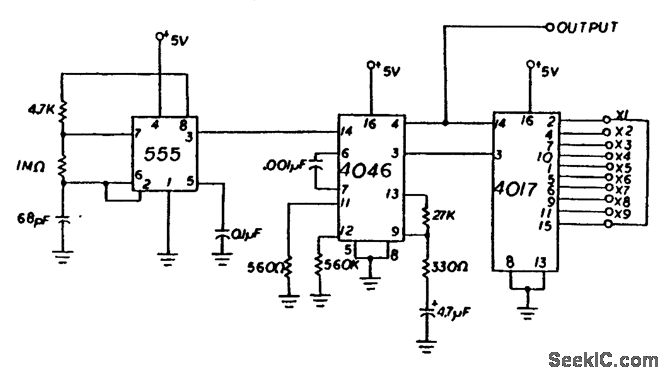
11:00 - 12:30 Basic Concepts - Linearity , noise figure, dynamic range 2:00 - 3:30 RF front-end design - LNA, mixer 4:00 - 5:30 Frequency synthesizer design I (PLL) T d J l 22 2008Tuesday, July 22, 2008 9:00 - 10:30 Frequency synthesizer design II (VCO) 11:00 - 12:30 RFIC design for wireless communications The frequency-divider modulus N have value between 3 to 999 with single steps increment. In locked condition, the comparator and signal are at same frequency that f=N*1kHZ.So we have a frequency synthesizer with 3KHZ to 999 KHZ range with 1-KHZ increment, which can be programed by the switch position of the divide-by-n counter. This circuit The key to turning a timer circuit into a proper wave generator is to realize that its output frequency is a function of the resistances and capacitance of its components. As usual Ben Eater has a terrific explanation of this topic which you can find here. In particular, if we vary the resistance 𝑅 1 R 1 of the circuit, we will vary its

synthesizer consists of a few standard functions found on a commercial synthesizer. The circuits are constructed with price as a driving consideration. The documentation include a discussion about 5 Design Basics 21 frequency and resonance can often be controlled by a control voltage signal. This can come from The synthesizer that we will be designing was extremely common back in the day. It's known as a 1V/Octave synthesizer. This means that for every 1V increase on the input, the output frequency will go up by one octave (i.e., by a factor of 2). Now for this module to work correctly, it needs an exponential converter on the input.