Light Meter Circuit with LED Bar Graph Circuit Diagram A light meter circuit is a device which detects the intensity of light through a light sensor, and displays the measured results on an analogue or digital meter. The main idea proposed in this article does not work with a cumbersome and fragile moving coil meter, rather it simply displays the light intensities through an array of LEDs.
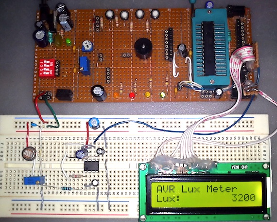
In this tutorial, we will learn to make LED based light meters using photo resistor/LDR (light dependent resistor) with Arduino. Instead of multiple LEDs we used led bar display which is nothing but a series of LED in a line inside the modular kit. Led Bar-Graph Display: The bar graph display - a combination of The LED emits constant-intensity light as long as the operating voltage (V B) remains constant (although the intensity decreases with increasing ambient temperature). You can vary the light intensity as required by changing the resistor value. For a standard LED of 5mm diameter, Figure 1 shows the forward voltage (V F) vs. forward current (I F
Simple Basic LED Circuit (How to Use LEDs) Circuit Diagram
Design# 2. The next two PIR based sensor LED light circuits is similar but has an added feature of detecting the ambient light conditions also. Therefore the circuits will respond based on whether the atmospheric light is sufficiently dark or not and also whether the premise is occupied by a human.
If you are operating the LED with a 9V power supply or battery then use a minimum value of 470 ohms resistor as current limiter for the LED. Step 4: 12 Volt Basic LED Circuit With 560 Ohms Resistor For operating an LED with a 12V power supply or battery use minimum 560 ohms value resistor, or you can also use 1K maximum value. Lumens (Lm) are the unit of measurement we use to quantify the amount of visible light the human eye can see. The luminous flux of a particular light source is measured in lumens. You may have noticed the lumens output printed on led bulbs available in market. More the lumens more will be the light intensity, spreading power and vice versa. LED Circuit Design. Learn how to design LED circuits. How to calculate resistor size, how to protect LED, how long will a battery power a circuit, how to calculate resistor power rating, how to connect LED and much more. Scroll to the bottom to watch the YouTube tutorial. LED. These are LED's, or light emitting diode.

Guide to LED Circuit Designs and LED Basics & Operation Circuit Diagram
SMPS 50 watt LED Street Light Driver Circuit. 12V, 24V, 1 Amp MOSFET SMPS Circuit. 5V, 12V Buck Converter Circuit SMPS 220V I own a couple cloud based subscription LED grow lights. I want to use these fixtures without the computer portion. Hello sir, I want to design a LED driver circuit for 15 white LED's in series. The total voltage

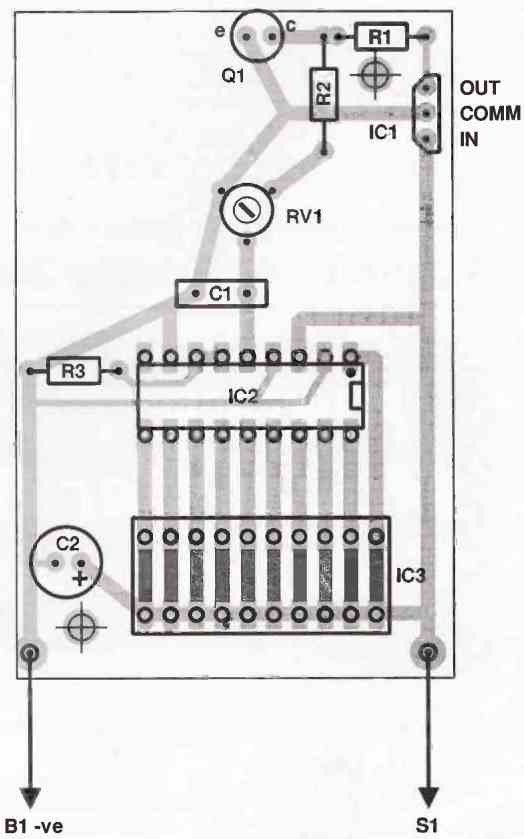
The voltage divider circuit include R2, R3 and VR1, to compare the circuit with the light meter calibration standard. How to setting May use A 40-watt incandescent bulbs without Reflector. Placed away from the light meter is 50cm.(which will be a brightness of 150 lux approx.) Then adjust VR1 to read the Vout is the number 150 (1.5V). In this tutorial, we are making a project on a moisture-level LED meter circuit. This circuit senses and measures humidity or moisture levels in plants, wood, floor, soil, wall, etc. you can buy different moisture detectors from the market but if you are someone who likes experimenting with electronics then you should definitely try this circuit.
