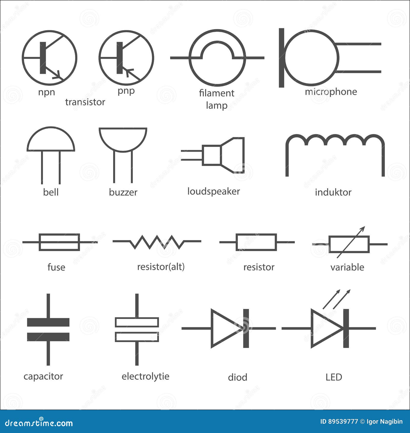
Inductor Symbols And Meanings Circuit Diagram 2.2 Electronics Symbols. An electronic symbol is a graphical representation used to represent electronic components or devices specifically in electronic circuits. Electronic symbols are similar to electrical symbols but are more specific to electronic components such as transistors, diodes, integrated circuits, and other electronic devices Learn the standard symbols for different electronic devices and how to draw circuit diagrams. Find the circuit symbols for wires, power supplies, resistors, capacitors, diodes, transistors, logic gates, meters, sensors, switches, audio and radio devices, output devices and more. Learn how to draw circuit diagrams using standard symbols for different electrical and electronic components. Find symbols for wires, switches, sources, resistors, capacitors, inductors, diodes, transistors, logic gates, amplifiers and more.

Learn the basic schematic symbols for batteries, capacitors, resistors, diodes, transistors, and more. See examples of different types of diodes, transistors, logic gates, ICs, and power symbols. As an electronics engineer, understanding circuit symbols is crucial for designing, troubleshooting, and innovating. This visual guide provides a comprehensive reference to essential electrical and electronic symbols used in schematics and PCB design. Whether you're working with diodes, transistors, logic gates, or passive components, recognizing these symbols speeds up the design process Circuit symbols are used in circuit diagrams which show how a circuit is connected together. The actual layout of the components is usually quite different from the circuit diagram. To

Electronic symbol Circuit Diagram
Learn the meaning and usage of electrical symbols and electronic circuit symbols for drawing schematic diagrams. Find tables of symbols for wires, switches, relays, resistors, capacitors, inductors, power supplies, meters, lamps, diodes, transistors, and more. Thus, some circuit symbols are not approved as a standard symbol. But I think most people can understand them. Learn more: about Electronic circuits. Wire Symbols Wire Circuit Symbol. Description: We use a wire to connect the electronic components to each other. All electrical and electronic components need wire to connect them to the circuit.

Learn how to use graphical symbols to represent electrical and electronic devices and circuits in schematic diagrams. Find the common and accepted symbols for power supply, resistor, capacitor, inductor, switch, diode, transistor, op-amp, and more.
The Most Common Schematic Symbols Used in Electronics Circuit Diagram
Learn about the pictograms used to represent various electrical and electronic devices or functions in a schematic diagram. See common symbols for wires, batteries, resistors, capacitors, diodes, transistors, and more.