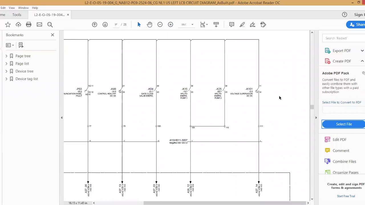
How to Read a Circuit Board Schematic Understanding Design Elements Circuit Diagram Reference Documentation: Referring to circuit schematics, layout diagrams, and related documents for a deeper understanding of the board's functionality and design. Testing Equipment Usage: Employing tools like multimeters, oscilloscopes for testing and analyzing components and circuits on the board.
Reading Schematics - Common Active Components. Active components are the heart of modern electronics. They are usually made of semiconductors. To perform tasks these components need a set level of voltage or they supply energy to the circuit. Voltage sources, current sources, generators, all components made of transistors, and all types of diodes are examples of active components. However, making the best use of these graphics requires that you know how to read a circuit board schematic effectively. How to Read a Circuit Board Schematic With Purpose. Throughout the PCBA development process, which includes design, manufacturing, and testing, the ability to read and understand PCB diagrams is essential. This begins with
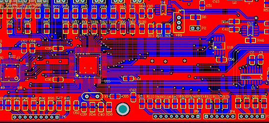
How to Read PCBs and Identify Components [Solve] Circuit Diagram
Transistors used in the circuit board diagram design are employable in either amplification of an electrical signal or just altering or turning ON/OFF an electrical signal. When using a circuit board to read a diagram the initial step is to know all the components that are employed in the circuit. Search for the mentioned standard symbols Learning how to read a printed circuit board (PCB) is an important skill for engineers and hobbyists. It helps you understand how a device works, troubleshoot problems, and even design new circuits. Let's break down the steps to reading a PCB into simple, actionable tips.

Schematic symbols and legends are the visual keys to understanding the circuit's design. Each symbol represents a specific component and its electrical properties. For example, an open rectangle with two vertical lines indicates a resistor, while a circle with a cross inside represents a capacitor.

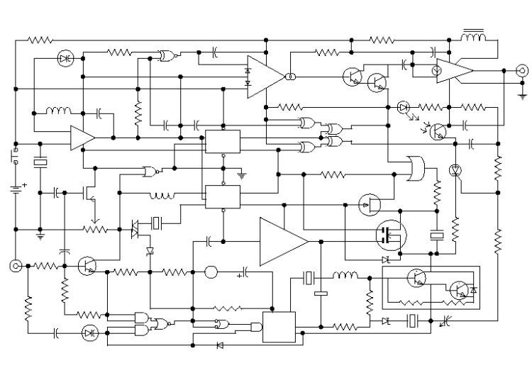
How to Read a Circuit Board: Mastering the Language of Electronics Circuit Diagram
This is a guide on how to read PCB schematics. A PCB schematic is a circuit diagram designers use in the first stage of the board design process. And the core components of these schematic diagrams are unique circuit symbols that all designers globally can understand. So knowing these schematics is paramount. Difference Between a Schematic and a PCB Layout. A schematic is like the map of your circuit. It's a logical diagram that shows how all the components are connected, without worrying about their physical placement.. On the other hand, a PCB layout is a physical representation of the circuit that's designed for manufacturing. It shows the exact placement of components on the board, as well Recommended Reading: PCB Design: A Comprehensive Guide to Printed Circuit Board Design. Advanced Circuit Board Analysis Signal Integrity and Impedance Control. Signal integrity and impedance control are critical considerations in high-speed circuit design, particularly as clock speeds and data rates continue to increase.