Highly Efficient 0 Circuit Diagram However, the dimming effect can be perhaps implemented by connecting the series LED section of the LED bulb with the IC 555 circuit, as indicated in the following diagram: We know that an LED bulb circuit is nothing but a small AC to DC SMPS circuit, which employs a small ferrite transformer for stepping down the mains voltage to a lower LED DC Automatic Light Dimmer Circuit Diagram. The light then comes on. When the light switch is turned off, C2 is discharged via P1, R2 and D6. When the potential across C2 drops, the brightness of the LED diminishes, so that the p.d. across R3 also drops. The increasing resistance of R3 effects phase angle control of the triac so that the light is
The LED dimmer circuit typically consists of several components, including a microcontroller or an integrated circuit that generates the PWM signal, a power transistor or MOSFET that controls the current flow to the LED, and a potentiometer or a digital control interface that allows the user to adjust the brightness level.
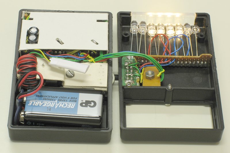
Automatic Lamp Dimmer Circuit using Triac Circuit Diagram
This automatic light dimmer circuit makes it possible to control a lighting system so that it turns on or off slowly. The circuit works this way: when switch S1 is closed, the capacitor C1 is slowly charged. Once the voltage at C1 reaches 0.6, transistor T1 begins to conduct and the LED also begins to light. The automatic Daylight dimmer circuit. But in Figure 2 will work to reverse the first. Also, choose the switch-S2 to LDR1 way, then this circuit becomes the automatic daylight dimmer switch circuit. This can control lamps in the Warehouse, if open the door and have sunlight to LDR, it will cause the lamp to glow. LDR1 in Figure 2 is a PTC type. Next onto the bottom half of the circuit, we will wiring the dimmer for the LED light and the transistor to control the turning on and off from the out of the 555 timer. Similar to the dimmer we do from step 2, the middle gate of the dimmer will connect to the output gate of 555 timer (Gate No.3), make sure to wire the 10K ohm resistor between
In this LED Dimmer Circuit, 555 timer works as an astable multivibrator and generates PWM pulses. The circuit includes the timing components like Resistors, potentiometer, and capacitor Thus, the potentiometer is there to adjust the duty cycle of the PWM signal. The higher the duty cycle, the greater will be the light intensity, the light WORKING OF AUTOMATIC LAMP DIMMER CIRCUIT: Triac and LDR holds the significant place in the working of this lamp dimmer. Here LDR (Light Dependent resistor) was used as a light sensor which offers high resistance to the current flow in the absence of light and low resistance when light incident on it. PWM LED dimmer circuit using IC 555; USB
Automatic Light Dimmer Circuit Diagram
Hii Friends, Today i am show you how to make a automatic light dimmer circuit at home. So let's start it. All Component details show in the video. So watch v
You'll make an automatic dimmer for an LED. Apart from sensors To create a closed circuit, the first leg of the LDR is connected to the 5 volt voltage and the last bit, the other leg of the resistor, is connected to the ground. Finally, you need one more wire to get some data from the sensor.
