Heartbeat Sensor using Arduino Heart Rate Monitor Circuit Diagram The circuit design of the Arduino based Heart rate monitor system using the Heartbeat Sensor is very simple. First, in order to display the heartbeat readings in bpm, we have to connect a 16×2 LCD Display to the Arduino UNO. For LCD connections please visit: The circuit design of Arduino based Heart rate monitor system using Heart beat Sensor is very simple. First, in order to display the heartbeat readings in bpm, we have to connect a 16×2 LCD Display to the Arduino UNO. The 4 data pins of the LCD Module (D4, D5, D6 and D7) are connected to Pins 1, 1, 1 and 1 of the Arduino UNO.
Explanation of DIY Heart Rate Monitor. Step 1: Gather materials To make a DIY heart rate monitor, you'll need the following materials: • An Arduino Nano microcontroller • A breadboard/PCB • A 16×2 LCD display • A photoresistor MAX30102 • Jumper wires • A battery pack.
Wireless and Wearable Heart Rate Monitoring Device Circuit Diagram
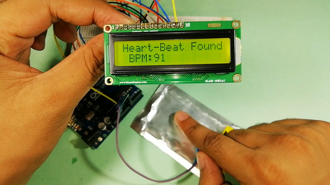
Overview. In this project, we will interface Pulse Sensor with Arduino to Measure Pulse Rate (BPM) or Heart Beat value. The Pulse rate will be displayed on 16×2 LCD Display. A pulse sensor is a hardware device that can be used to measure heart rate in real-time. When paired with an Arduino microcontroller, you can create a simple yet effective heart rate monitor.

Once you design your heart rate monitor, use this page as a starting guide for what parts to purchase. Most of the parts you need should be available from an electronics vendor like SparkFun Electronics or Adafruit Electronics. Pulse sensor ; Arduino board; If you are building a stationary/bedside heart rate monitor, the Arduino Uno R3 is a

Homemade Arduino Heart Rate Monitor Project Circuit Diagram
In this article, we will discuss pulse sensor and Arduino Uno and build a full responsive Heart Rate Monitor using character LCD, Amped Pulse Sensor Amped and Arduino Compatible Plug and Play Heart Rate Sensors.. It can be used by students, artists, athletes, manufacturers, games and mobile developers who can easily incorporate live heart rate data into their projects. Heart rate is calculated by taking a continuously updated rolling average of the periods between pulses. The length of the rolling average can be adjusted by modifying the value of #define MAX_BPM_ARRAY_SIZE. The longer you make it the slower the updates, but the better the approximation (assuming the finger is kept steady in the sensor).

This project involves developing a Heart Rate Monitoring Device using an Arduino UNO, an analog heart rate sensor, an OLED screen, an HC-05 Bluetooth module, a piezo buzzer, a vibration motor, and an LED.The system continuously monitors heart rate and displays it on an OLED screen. Additionally, it transmits the heart rate data to a smartphone app via Bluetooth for remote monitoring with a While we progress with that, in this session, we will build a wearable Arduino heart rate monitor to measure the heart rate of a remote patient. Step 1: Components Required. The following are the components required to build your Wearable Arduino based Heart Monitoring System. Arduino Nano R3; nRF24 Module; Adafruit NeoPixel Ring: WS2812 5050
