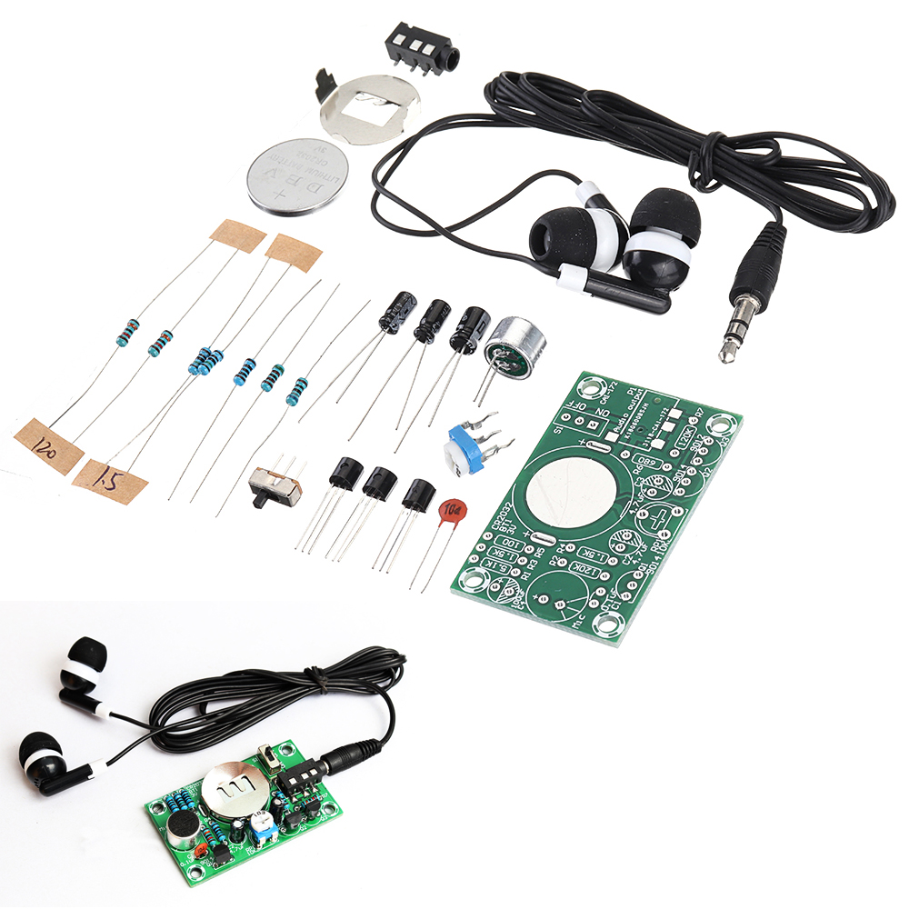
Enabled by Design Circuit Diagram Researchers at the Georgia Institute of Technology (Georgia Tech) have taken the matter into their own hands and have developed a hearing aid device that costs as low as $1 and is open-sourced for A simple hearing aid circuit using 1.5V battery offers a low power way to amplify sounds. While it can be a learning experience to build these circuits have limitations. They may not work for all hearing loss needs and offer less functionality compared to professional hearing aid. This low-cost, general-purpose electronic hearing aid works off 3V DC (2x1.5V battery). The circuit can be easily assembled on a veroboard. For easy assembling and maintenance, use an 8-pin DIP IC socket for TDA2822M. Circuit Diagram: Parts: P1 = 10K R1 = 2.2K R2 = 330K R3 = 680R R4 = 33R R5 = 100R
This device also has a very easy user interface to keep operation quick and simple. The block diagram above outlines how the hearing aid works. A signal picked up by the microphone first goes through a pre-amp stage which culls frequencies above 3kHz (outside hearing spectrum) and then amplifies the remaining signal for future stages. how to make hearing aid at home।diy hearing aid circuit।hearing aidsDiy Amazing Simple Powerful Hearing Aid Machine At Home. Watch full video don't miss any Introduction to Hearing Aid Circuits Hearing aids are essential devices for individuals with hearing impairments, enabling them to better perceive and understand sounds in their environment. While commercial hearing aids can be expensive, it is possible to create a simple and affordable hearing aid circuit as a DIY project. In this article, we will explore […]
OP AMP BASED HEARING AID : 5 Steps Circuit Diagram
Millions of people experience hearing loss, but conventional hearing aids are often expensive and complex. This project provides an affordable, DIY solution—a Wearable Hearing Aid that you can make using simple, non-programmable electronic components.. This compact device captures and amplifies sound, delivering it through any standard earphones.
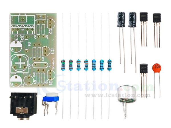
This low-cost, general-purpose electronic hearing aid works off 3V DC (2×1.5V battery). Fig. 1: Hearing aid circuit. In this circuit, transistor T1 and associated components form the audio signal preamplifier for the acoustic signals picked up by the condenser microphone and converted into corresponding electrical signals. It will increase the volume up. Make us hear all the levels. Both many and the less sound. And we can adjust the volume as needed. To set the volume to a level that is appropriate for each person. Read Also:Active microphone preamplifier using LF356. How it works. Look in the circuit below. It is a complete circuit of a hearing aids project.

Cheap & Small hearing aids circuit project Circuit Diagram
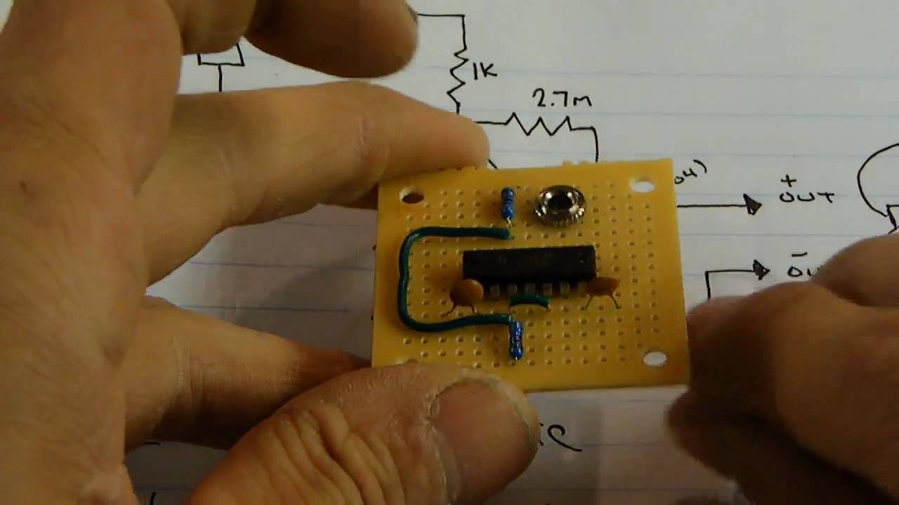
OP AMP BASED HEARING AID: In this instructable i am going to show you how you can build a simple hearing aid with an op amp. The device can amplify the sound up to 5 times.The making of the hearing aid is also very simple and would not take more than an hour.The output of th…