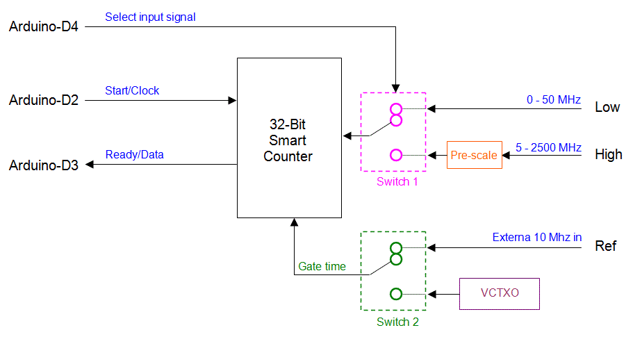
Electronic Component and Circuit Diagram In this post, we'll explore how to build a high-frequency counter using an Arduino and an LM311 comparator. This setup enables accurate frequency measurement of various signal waveforms, such as sine, square, triangle, and sawtooth, with frequencies up to and beyond 6 MHz.

Electronic counters, also known as frequency counters, use digital circuits to measure the frequency of an input signal. They work by counting the number of cycles or pulses in a given time interval and then calculating the frequency based on this count. In this guide, we will focus on building a high frequency counter using an Arduino board. In Visuino, at the bottom click on the "Build" Tab, make sure the correct port is selected, then click on the "Compile/Build and Upload" button. Step 6: Play If you power the Arduino UNO module, the OLED Display will start to show the frequency in Hz that 555 module produces.

Frequency Measurement using Arduino Circuit Diagram
The pulseIn() function can count pulses with a time period ranging from 10 μS to 3 minutes. A circuit diagram of the frequency counter using Arduino is given below. Potentimeter R1 is used to adjust the contrast of the LCD screen. Resistor R2 limits the current through the back light LED. Definition. Frequency is the number of complete cycles per second in alternating current direction. The standard unit of frequency is the hertz, abbreviated Hz.. Frequency Measurement Frequency Measurement is carried out by measuring the number of cycles in one second, this method requires time of one second. Other method is to measure time period of one cycle F = 1 / T.

Frequency Counter using Arduino. Published June 13, 2016 40. Dilip Raja Author This post shows how to build a frequency counter device using Arduino UNO board where signal frequency value is displayed on 1602 LCD screen. With this counter we can measure frequency of PWM signals with peak voltage of 5V. Related Project: 220/380V AC Frequency Meter with Arduino.

Arduino Projects - Simple Circuit Circuit Diagram
The aim of the project is to design a simple digital frequency counter circuit using Arduino UNO and 555 Timer IC. The working of the project is very simple and is explained here. As mentioned earlier, the 555 Timer IC is configured to operate in Astable mode. Hence, the output of the 555 Timer IC (or rather the signal generator circuit) is a
