Diploma Frequency Counter Circuit Circuit Diagram Arduino frequency counter circuit: Project circuit diagram is shown below. The 16×2 LCD screen (2 rows and 16 columns) is used to display the values of frequency and period of the input voltage where: RS —> Arduino digital pin 2 E —> Arduino digital pin 3 D4 —> Arduino digital pin 4 D5 —> Arduino digital pin 6 D6 —> Arduino digital pin 7

The offset frequency is the same as the intermediate frequency in many cases, because the counter is usually connected to the receivers VFO (variable frequency oscillator). For this purpose, a programming mode (aka "setup mode" ) has been implemented in the firmware so you can enter an offset frequency without reprogramming (or even
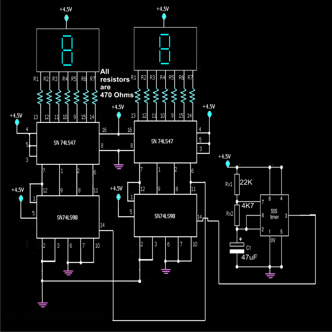
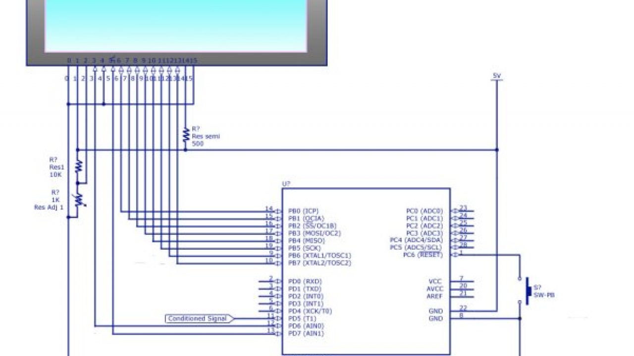
5 Digit Frequency Counter Circuit Circuit Diagram
Figure 2 Schematic of the frequency counter. You'll also notice the addition of an analog conditioning circuit feeding the input of the counter. To keep the design simple, only a Schmitt trigger inverter, a cap, and a couple of resistors are used. This is a well-known circuit dating at least back to the 1975 Fairchild application note 140.
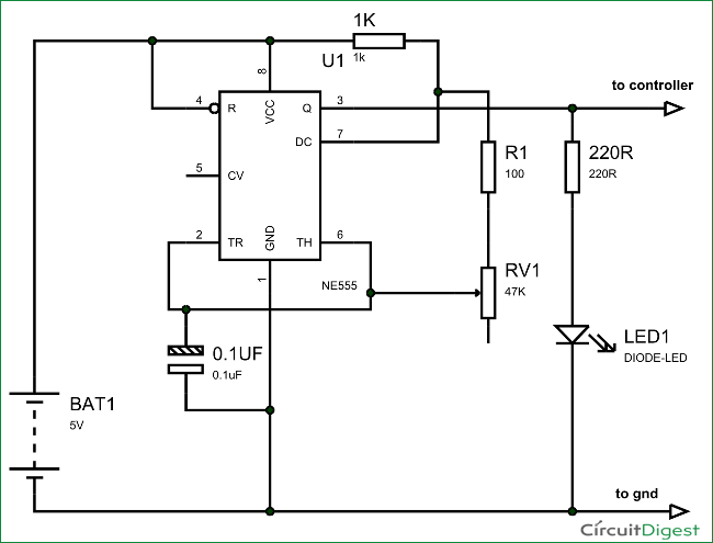
The aim of the project is to design a simple digital frequency counter circuit using Arduino UNO and 555 Timer IC. The working of the project is very simple and is explained here. As mentioned earlier, the 555 Timer IC is configured to operate in Astable mode.
Arduino Frequency Counter Tutorial with Circuit Diagrams & Code
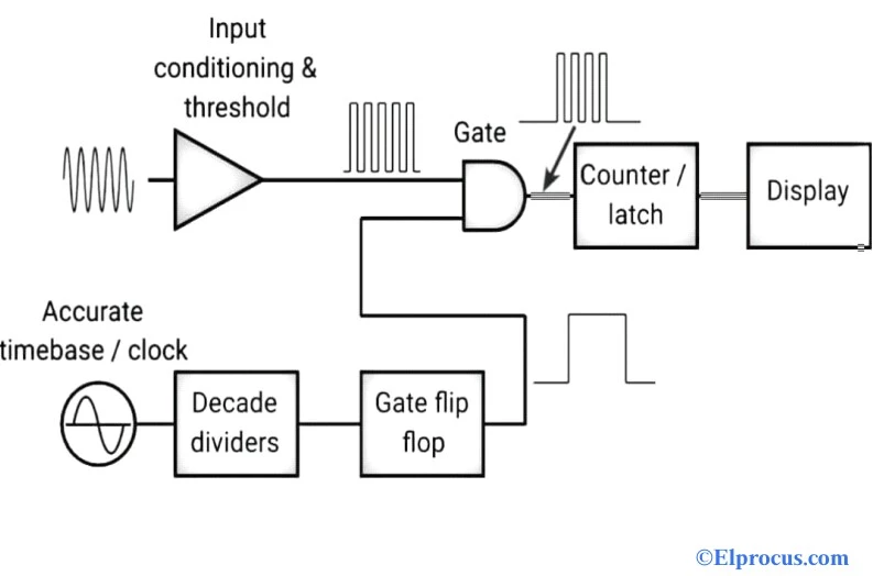
That's the maximum number of digits the shown counter design can display at the maximum. then simple the number of modules can be connected in series as described.The simple frequency counter circuit shown below will effectively convert any pulse at its input into a display over the 7- segment cathode block.The IC has an internal BCd to 7
If the frequency input is removed, the count over the display will get latched and remain available until the switch S1 is pressed, or the power is switched OFF and ON again. PCB Design for the 5 Digit Frequency Counter. The following image shows the track side PCB layout for the 5 digit frequency counter circuit. 10 MHz Digital Frequency Meter Here we design a simple frequency counter system using two timers and two counters. While one of the Timer IC is used to produce clock signals, the other is used to produce the time limited signal of one second. Frequency Counter Circuit Design. As I have used Arduino to generate the Square Wave, all I need is a few lines of code and access