Bridge Rectifier Circuit Diagram Types Working Its Applications Learn how to convert AC to DC using a bridge rectifier, a circuit made of four diodes arranged in a bridge configuration. See the circuit diagram, waveform, and operation of a bridge rectifier and its applications in various electronic systems.
Learn how to convert AC voltage into pulsating DC voltage using four diodes in a bridge configuration. See the full wave rectifier circuit diagram, output waveform, and how to add smoothing capacitors.

Bridge Rectifier Circuit Diagram And Waveform
Learn how a bridge rectifier converts AC into DC using four diodes and a load resistor. See the diagram, the working principle, and the characteristics of this full wave rectifier circuit. Learn how to convert both half cycles of AC to DC using a bridge rectifier with 4 diodes. See the circuit diagram, input and output waveforms, and analysis of peak current, output current, DC voltage, and ripple factor. A bridge rectifier diagram is similar, to a representation that illustrates the arrangement of components within a specific circuit. Its purpose is to convert alternating AC which is characterized by wave patterns into direct current (DC) that provides a consistent flow of electricity.

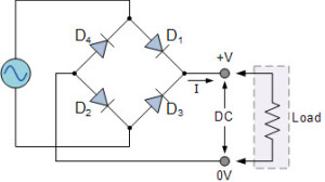
Key learnings: Bridge Rectifier Definition: A bridge rectifier is a circuit that converts AC to DC using four diodes arranged in a bridge configuration.; Working Principle: It works by allowing current to flow through different pairs of diodes based on the input polarity, ensuring the output polarity remains the same.; Circuit Diagram: The diagram includes four diodes connected to an AC input Learn how to convert AC voltage into DC voltage using four diodes in a bridge configuration. See the circuit diagram, waveforms, formula, advantages, and disadvantages of full wave bridge rectifier.
Diode Bridge: Four Diodes That Convert From AC to DC Circuit Diagram
Learn how to convert AC to DC using a bridge rectifier circuit with four diodes and a transformer. Find out the advantages, disadvantages, and types of bridge rectifiers and their applications in electronic power supplies. Learn how to use four diodes to convert AC to DC with a diode bridge rectifier circuit. See the diagram, how it works, and what it's used for in power supplies and other circuits.
