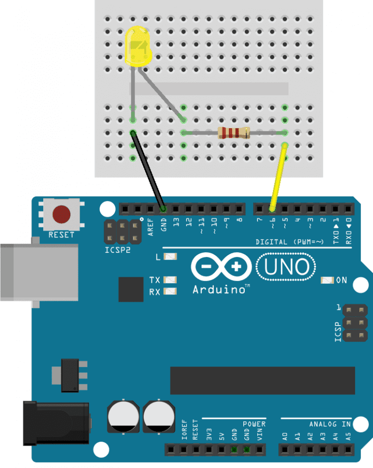
Arduino lesson 08 Pulse Width Modulation Circuit Diagram In this tutorial, we will learn about Pulse Width Modulation (PWM) using an Arduino controller. Pulse Width Modulation, a crucial technique in electronics, allows us to generate variable-width pulses to represent analog input signal amplitudes. We will explore how the analogWrite() function in the Arduino IDE facilitates PWM generation. But before we dive into the In this tutorial we will show different application examples of PWM(Pulse Width Modulation) using Arduino Nano.First we explain briefly about PWM, then explain how to generate PWM signal with Arduino Nano. Afterwards we show different application example of PWM which includes controlling brightness of a LED with software alone and using Potentiometer, control of motor and sound generation. Arduino Pulse Width Modulation (PWM) In this project, we will control the brightness of an LED connected to the Arduino UNO board with the help of PWM technique. The schematic required for the implementation of the project is shown in the below image. In this circuit, the anode of an LED must be connected to any of the PWM pin of the Arduino UNO.
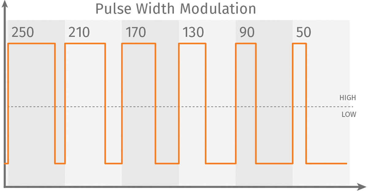
Pulse width modulation PWM: PWM stands for pulse width modulation which consists of a square wave with the help of which we can control the up or high time. It is simple but digital way to control the digital signals that we use to vary the energy that is send to a load or to encode information within the signal. Pulse Width Modulation (PWM) is a technique used in electronics to control the amount of power delivered to a device by varying the width of the pulses in a digital signal. In simpler terms, PWM allows you to control the "average" voltage or power supplied to a device by turning the signal on and off at a rapid pace. The Fading example demonstrates the use of analog output (PWM) to fade an LED. It is available in the File->Sketchbook->Examples->Analog menu of the Arduino software. Pulse Width Modulation, or PWM, is a technique for getting analog results with digital means. Digital control is used to create a square wave, a signal switched between on and off.

Pulse Width Modulation with Arduino: An In Circuit Diagram
Some Useful Arduino Functions Related to Analog Pins analogWrite() Function. The Arduino analogWrite() function is used to generate a Pulse Width Modulation signal on a digital pin of the Arduino board.. Syntax: analogWrite (pin, value); Parameters: It takes two parameters: Pin: It specifies the digital pin number where the PWM signal will be generated.; Value: This parameter specifies the Pulse-width modulation (PWM) can be implemented on the Arduino in several ways. This tutorial explains simple PWM techniques, as well as how to use the PWM registers directly for more control over the duty cycle and frequency. This tutorial focuses on the Arduino Diecimila and Duemilanove models, which use the ATmega168 or ATmega328. Goals Pulse width modulation (PWM) is an essential skill for makers, hobbyists, and engineers alike. It allows microcontrollers like Arduino to control power delivered to electrical loads in an analog fashion using digital pins. In this in-depth guide, we will start from the basics - understanding what PWM signals are, how PWM works, and how it […]
The pin argument is the pin number where the pulse width modulation signal will be generated. The value argument is the analogWrite value that corresponds to the duty cycle of the pulse width modulation signal. To find the analogWrite value that will produce a pulse width modulation signal with a specific apparent voltage, use this formula: