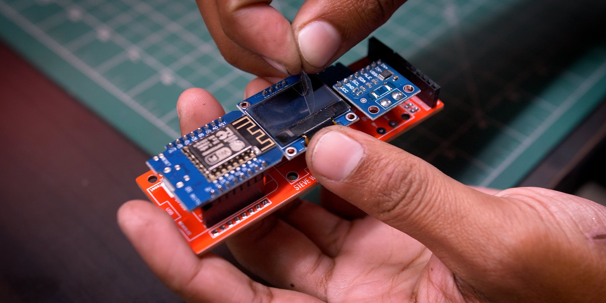
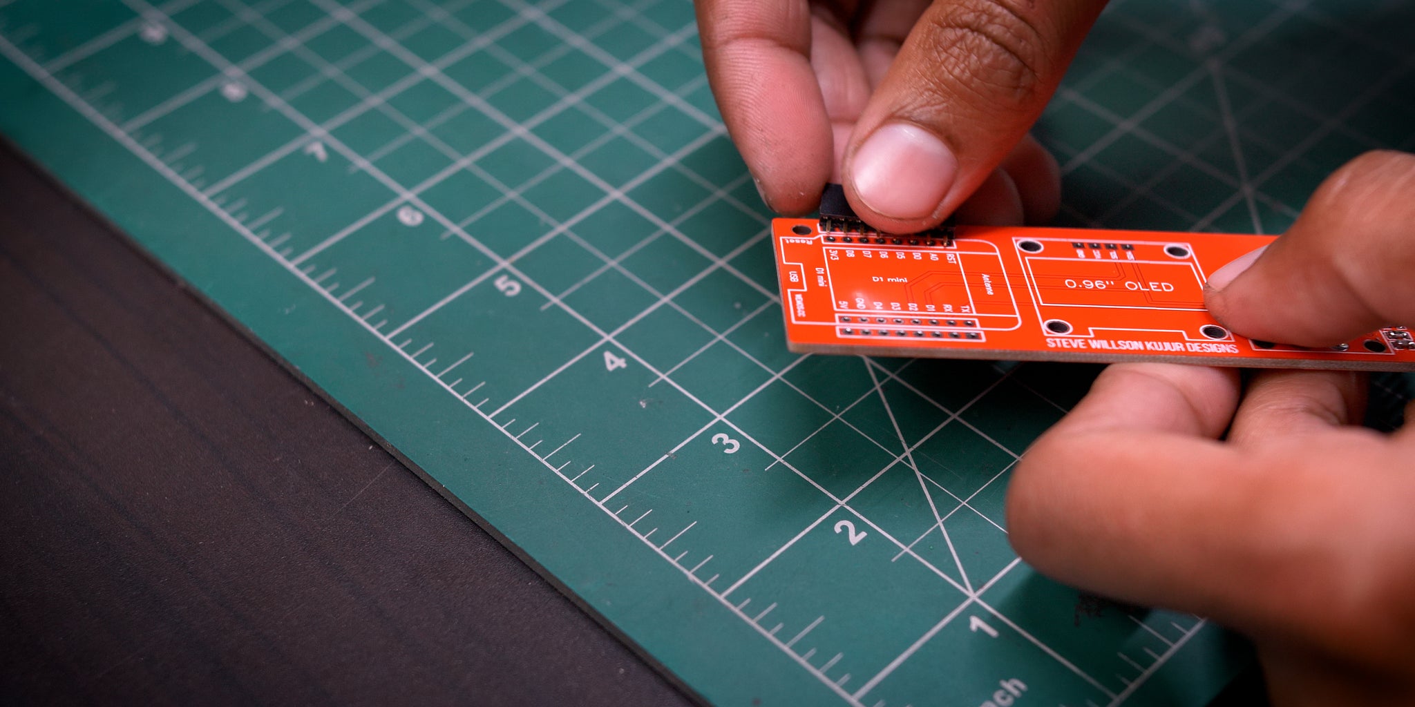
100VDC 100A 16 Steps with Pictures Circuit Diagram If you are going to be installing your power meter somewhere permanently then you may want to solder the resistors and capacitor directly onto the CT so that they cannot come loose. If you are simply trying this project for fun then a breadboard is perfect. The basic circuit for the connection of the CT to the Arduino is shown in the images ATtinyPowerMeter: This instructables show how to make a simple power meter using 3 components: ATtiny85, INA219 and OLED module. It can continuous measure the voltage(V), current(mA) and accumulated power usage(mWh). Step 5: Circuit Design. Here is the connection summary: Battery +ve -> switch -> ATtiny85 pin 8, INA219 module Vcc, OLED
put Vs power meter reading. The meter plot is similar. If you don't have access to a quality signal generator, you can calibrate the power meter using a low-power transmit-ter. A power level of 1 to 2 W at 7 MHz is fine. Attach the transmitter through the tap to a dummy load where the output voltage can be read directly using a di-
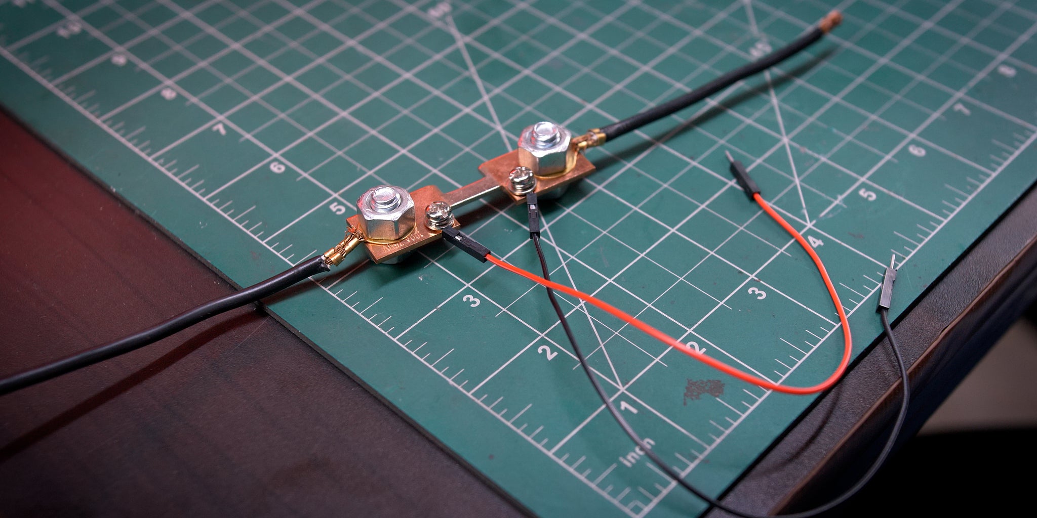
power measurement Circuit Diagram
Electromechanical energy meters have been the standard for metering electricity since billing began. But these are now being gradually replaced by electronic digital energy meters. Presented here is a simple energy meter using Analog Device's ADE7757 chip for single-phase, 2-wire (phase and neutral) systems used in households. Installation of Single Phase kWh Meter (1-Phase, 2 Wires, 230V AC Energy Meter) First of all, make sure to disconnect the main power before working on electrical installations. Starting from the left side for MAIN, connect the incoming (from transformer) Phase (Line) wire to to the 1st slot on the meter (Main).

Simple RF-power measurement. Making power measurements from nanowatts to 100 watts is easy with these simple homebrewed instruments! (-70 dBm). A tap circuit supplements the power meter, extending the upper limit by 40 dB, allowing measurement of up to 100 W (+50 dBm). Figure 1 - Schematic of the 11- to 500-MHz wattmeter. Unless otherwise So In this Instructables, I am going to show you how to make a simple wifi-enabled AC Energy Meter by using Arduino/Wemos board. By using this Energy Meter, you can measure the power consumption of any home appliance. Now the power required for the circuit board (Wemos, OLED, and ACS712) is taped off after the spring-loaded connector. To
How to Make a Digital Voltmeter, Ammeter Module Circuits Circuit Diagram
The transistors are BC640, however you may try other transistors like 8550 or 187 etc. The proposed digital voltmeter, ammeter circuit module can be effectively used with a power supply for indicating the voltage and current consumption by the connected load through the attached modules. Referring to the circuit diagram below, the 3 digit digital display module is build through the ICs CA 3162 Overview. In this project, we will interface PZEM-004T (a compact AC power monitoring module) with Arduino to build a single phase AC Energy Meter. PZEM-004T Current and Voltage reader is a module that can measure current, voltage, active power (W), energy (kWh), frequency, and power factor.The module uses Modbus-RTU, a standard protocol for industrial communication.