10 Band Audio Equalizer Circuit Diagram Tone control or Active equalizer circuit especially bass, treble, and MID control based Equalizer is an important circuit in audio amplifier design. Generally, three-stage active Equalizer filters require three control bass, treble, and MID. The bass control allows the low frequency to pass but blocks high frequency and the treble control portable speakers, headphones, and home audio systems. The 5-band equalizer is one of the most often utilized kinds of audio equalizers in both home and business settings. Because it offers a more accurate degree of control over the sound than the more straightforward tone controls used in entry-level audio systems, this kind of equalizer is
An equalizer schematic is a vital component in audio systems, allowing for precise control over the frequency response and tonal balance of a sound signal. Whether in professional recording studios, live concert setups, or home audio systems, equalizers play a crucial role in achieving the desired sound quality. It is commonly used in audio systems to shape the sound according to preference or to compensate for the acoustic properties of a room. The circuit diagram of an audio equalizer typically consists of filters, amplifiers, and control circuitry. it is possible to design an audio equalizer circuit that effectively modifies the frequency
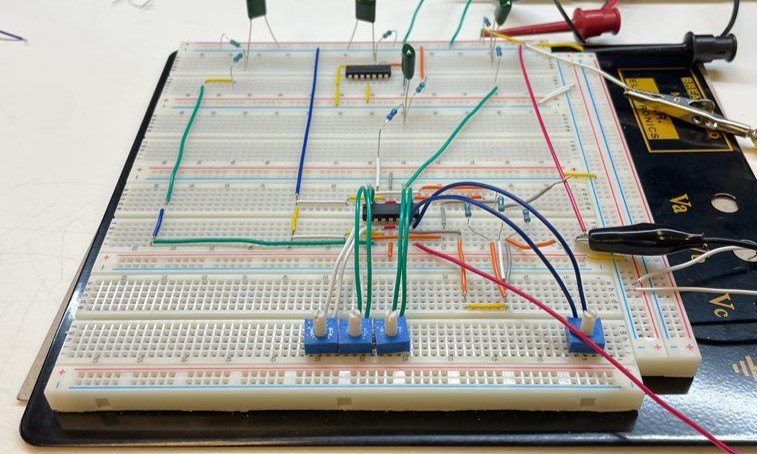
Building a Three Channel EQ on a Breadboard Circuit Diagram
An audio circuit collection, Part 3 Introduction This is the third in a series of articles on single-supply audio circuits. The reader is encouraged to review Parts 1 and 2, which appeared in the November 2000 and February 2001 issues, respectively, of Analog Applications Journal. Part 1 concentrated on low-pass and high-pass filters.
In this audio equalizer, we use the LF351* op amp. It is an integrated circuit and it uses an 8-pin dual in-line package, which can easily plug into the breadboard. There is no specific ground connection. For our circuit, use op amp power supply voltages of 12V for the positive terminal (pin 7), and ground the negative power terminal (pin 4). The goal of an audio equaliser circuit diagram is to create the flattest sound possible, with no emphasis or dip in any area of the frequency spectrum. and bass frequencies. The process begins by defining the desired gain and frequency response of the system. From there, components are added and configured into the circuit until the desired
HiFi Audio Circuit Design Circuit Diagram
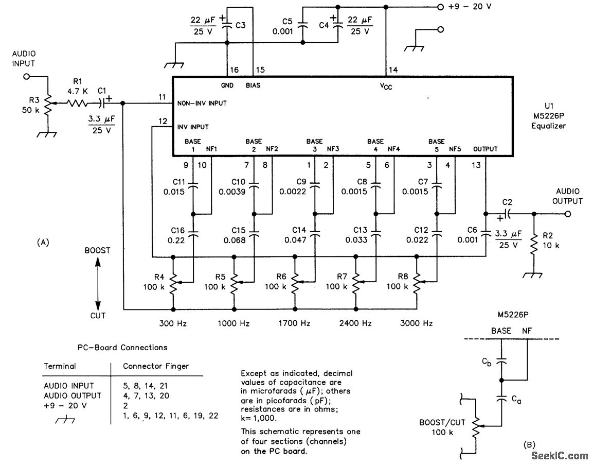
HiFi Audio Circuit Design A sound system is mainly composed of the auditory system (human ears), hardware system (equipment), software system (signal source) and listening environment. Figure 1 shows the typical block diagram of an audio reproduction hardware system, which converts the digital audio source to the voltage signal that In the previous tutorial, an audio crossover was designed using high pass and low pass audio filter. In this tutorial, an audio equalizer will be designed. An Equalizer (abbreviated as EQ) is an audio equipment which cut or boosts the certain frequency components from the audio signal. This process of adjusting the frequency components is called as Equalization.The equalizers are widely used If you're an audio enthusiast or someone who enjoys fine-tuning the sound quality of your audio system, building a 5 band graphic equalizer circuit can be a rewarding project. A graphic equalizer allows you to adjust the frequency response of your audio system, enhancing or reducing specific frequency ranges to suit your preferences.